Automatic Railway Gate Controller with High Speed Alerting System
The main aim of this
project is to operate and control the unmanned railway gate in the proper
manner in order to avoid the accidents in the unmanned railway crossing. In a
country like ours where there are many unmanned railway crossings, accidents
are increasing day by day. These train accidents are due to the absence of
human power in the railway. In order to overcome the accidents due to the above
problem we have planned to design the project.
Automatic Railway Gate
Control System with High Speed Alerting System is an innovative circuit which
automatically controls the operation of railway gates detecting the arrival and
departure of trains at the gate. It has detectors at the far away distance on
the railway track which allows us to know the arrival and departure of the
train. These detectors are given to microcontroller which activates the motors
which open/close the railway gate correspondingly.
Another feature of this
circuit is that it has an intelligent alerting system which detects the speed
of the train that is arriving. If the speed is found to be higher than the
normal speed, then the microcontroller automatically activates the alarm
present at the gate. This alerts the passengers at the railway crossing on the
road about this. Also This circuit has the feature for Identification of train
from other intruders i.e, animals etc .This can be implemented in manned level
crossings also, as manual errors can be eliminated by automation.
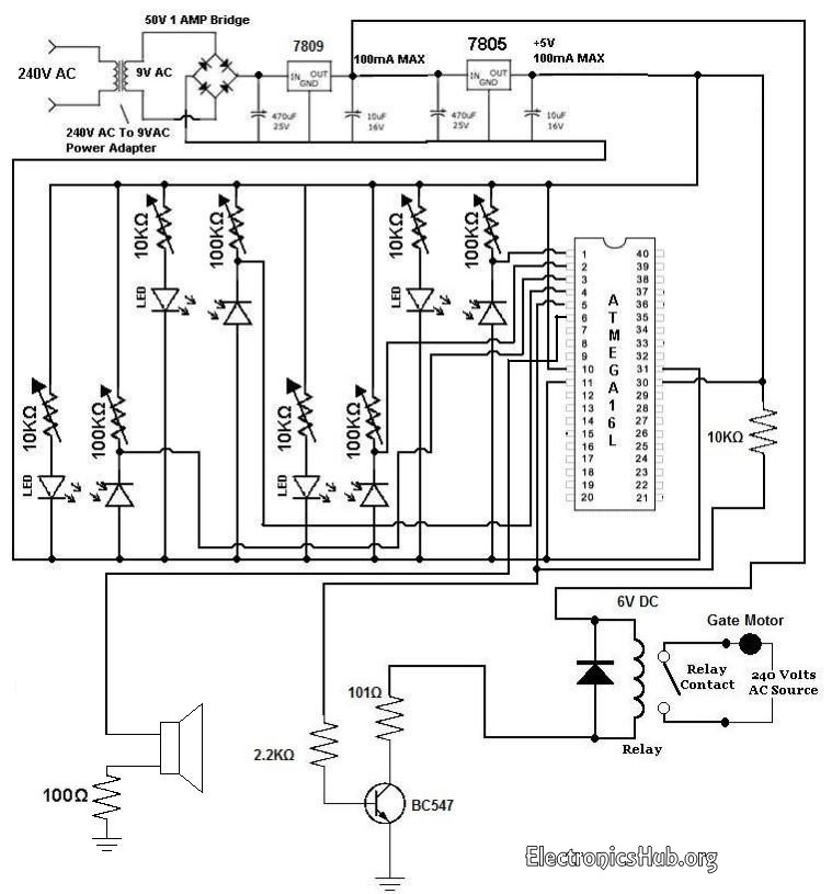
Circuit
Diagram of Automatic Railway Gate Controller:

Circuit Operation:
The operation of the
circuit can be clearly explained as follows. Basically the circuit consists of
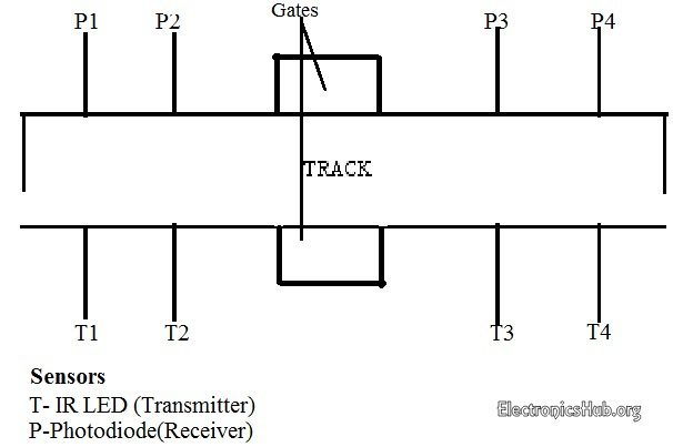
four IR LED-Photodiode pairs arranged on either side of the gate such that IR
LED and photodiodes are on either side of the track as shown in the figure
below.
Initially transmitter is
continuously transmitting the IR light which is made to fall on the receiver.
When the train arrives it cuts the light falling on receiver. Let us assume the
train is arriving from left to right, now when the train cuts the 1st sensor
pair a counter is activated and when it crosses 2nd sensor pair the counter is
stopped. This counter value gives the time period which is used to calculate
the velocity of the train.
The sensor2 output is
sent to microcontroller which makes the relay activate which causes the gate to
be closed. Now when the last carriage of the train cuts the sensor4
microcontroller de-activates the relay and gates are opened.
How does the sensor know
the last carriage?
Here as previously
mentioned the counter value is used to calculate the velocity of the train,
which means that every wheel of the carriage cuts the sensor pair within small
fraction of time based on its velocity. After the last carriage is passed there
is no obstacle to the sensor pair within that fraction of time hence it knows
that the train has left.
One more feature of this
circuit is detecting a train accurately i.e, there may be a chance that some
obstacle (for e.g some animal) may cut the sensor then in such a case the
counter is made to run for certain period of time (this time period is set
considering the possible lowest speed of train) if the obstacle does not cut
the 2nd sensor before this predefined time then this obstacle is not considered
as train and gates remain opened.
One more advantage of
calculating the velocity of train is, if the speed of the train crosses a limit
i.e, if it is traveling at an over speed then the passengers are alerted using
a by activating a buzzer.
The system basically
comprises two IR LED – Photodiode pairs, which are installed on the railway
track at about 1 meter apart, with the transmitter and the photodiode of each
pair on the opposite sides of the track. The installation is as shown in the
block diagram. The system displays the time taken by the train in crossing this
distance from one pair to the other with a resolution of 0.01 second from which
the speed of the vehicle can be calculated as follows:
Speed (kmph) =
Distance/Time
As distance between the
sensors is known and constant, the time is counted by the microcontroller and
from this information, we can calculate the speed.
This circuit has been
designed considering the maximum permissible speed for trains as per the
traffic rule.
The microcontroller is
used to process the inputs that are provided by the sensors and generate the
desired outputs appropriately.
No comments:
Post a Comment